Build and set up a WiFi Tally
The WiFi Tally is a piece of hardware that connects to the Hub via WiFi.
You do not need any prior experience with hardware projects as this is really beginner friendly.
Info
Please note that this is the Getting Started Guide, and we follow one opinionated path here. We don't want to confuse new readers with too many options and alternate paths to choose from. If you are curious about alternatives, check out details in the reference.
Requirements
You need a few parts to build the WiFi Tally.
a NodeMcu ESP8266
This is an ESP8266 wifi chip on a development board that is typically used for IoT applications. As it is an Open Hardware project there are lots of different boards available. They mostly differ in price and form factor and are all fit for the project. But they all look similar to this:
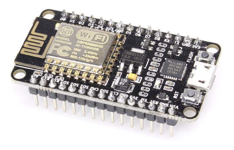
"NodeMCU Amica" by "Make Magazin DE", CC-BY-SA-4.0
!TODO: elaborate on different NodeMCUs!
a piece of RGB LED strip
It needs to be specified for 5V and have a common anode. Most LED strips that can be separated after every LED and have 4 pins should fulfill that requirement.
I recommend taking one with 120LEDs per meter to not have the LEDS be spaced too much.
an USB power source
The whole setup draws far less than 200mA and can be powered via USB.
- Some cameras have USB outlets that you can use
200mAis little enough that even the smallest power bank can supply the Tally for hours- use any old USB charger
Connect the hardware
All you need to do is connecting the LED strip to the NodeMCU board.
Warning
Do not connect more than 5 LEDs to the board!
This will drain too much current through the board and potentially damaging it.
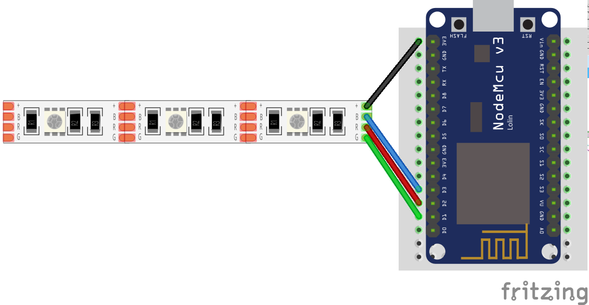
| board PIN | strip PIN |
|---|---|
| D3 | B |
| D2 | R |
| D1 | G |
| 3V3 | + or +5V |
Info
It is possible to connect the +5V pin of the LED strip to Vin on the board. But not all NodeMCU boards connect
the PIN to the USB power supply and your LEDs would stay dark.
It might also happen that you LED Strip does not work with a lower voltage of the 3.3V output. Typically this does not happen, but it could if you have an older strips.
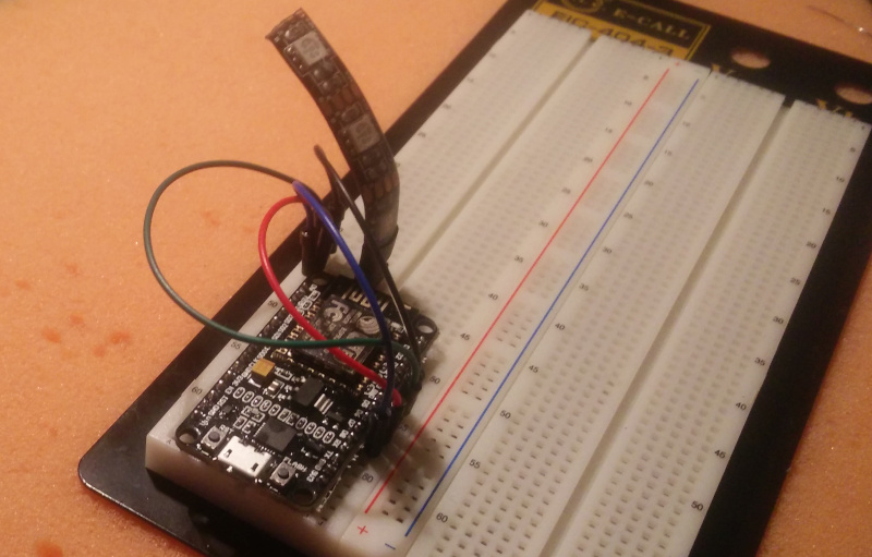
This is how the setup could look like on a breadboard.
Separate Operator and Stage Light
You can connect a second strip to use as an indicator for the speaker on stage. Connect the first LED as above and direct it in the direction of the camera operator. Then connect a second strip and let it face to the front of the camera.
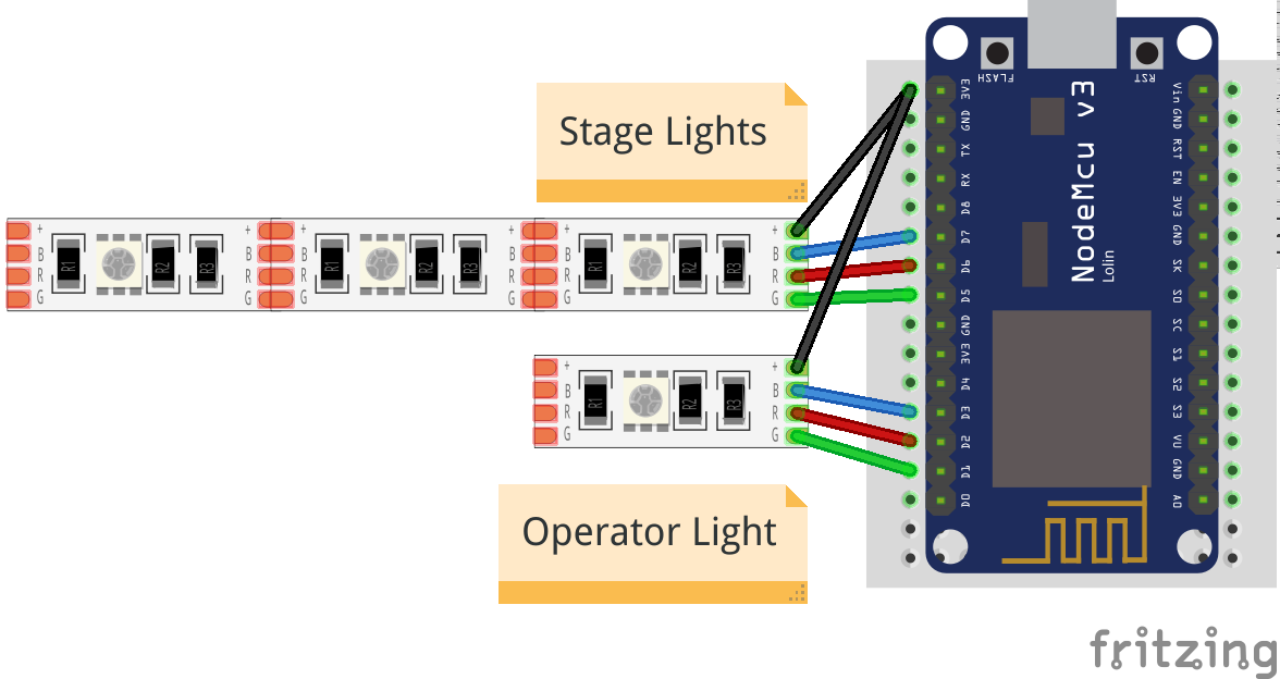
| board PIN | strip PIN |
|---|---|
| D7 | B |
| D6 | R |
| D5 | G |
| 3V3 | + or +5V |
This light will only show preview and live states, but not any error states.
Prepare the NodeMCU Toolchain
The NodeMCU documentation very nicely explains all the steps necessary to start a NodeMCU project. The documentation might seem overwhelming at first, but you only need to care of the two steps
- Flash Firmware, and
- Upload code
Depending on your Operating System, you should select one – and only one – tool for each of these steps from the table.
So either select NodeMCU PyFlasher or esptool.py to flash the firmware and follow their installation instruction. Similarly select ESPlorer or NodeMCU Tool to upload code and follow their installation instruction.
Download vtally-0.5.1-esp8266.zip for the latest files for the ESP8266.
Flash the firmware
When everything is set up flash the firmware with the tool selected in the previous step.
The firmware is the .bin file in vtally-0.5.1-esp8266.zip.
Upload Code
Use the tool you have selected to upload the following files from vtally-0.5.1-esp8266.zip to the NodeMCU board:
- every file ending in
.lc init.lua- the
tally-settings.inidescribed below
tally-settings.ini
This file configures your Tally. You can copy tally-settings.ini.example over and edit it as needed.
| setting name | description |
|---|---|
station.ssid |
The name of the WiFi that the Tally should connect to |
station.password |
The password to connect to the WiFi. If the WiFi has no password, leave it empty. |
hub.ip |
The IP address the hub is running on |
tally.name |
How you want this tally to be labeled in the hub. This name needs to be unique amongst all tallies in your network. It must not be longer than 26 characters. Use of ASCII characters is recommended. |
For a list for all configuration values see tally-settings.ini Reference.
Reboot the NodeMCU board by pressing the RST button on the board or disconnecting it from power briefly.
Success
If the LED strip starts blinking blue, this means you have correctly connected the hardware, flashed the firmware and uploaded the code.
After a few seconds it should show up in the Hub. Configure a channel there and the WiFi Tally should follow it.
Well done!
Info
If you run into problems, the Troubleshooting Guide should have you covered.
Conclusion
This concludes the Getting Started Guide.
To learn of other options for the Tally Light, see the reference.